|
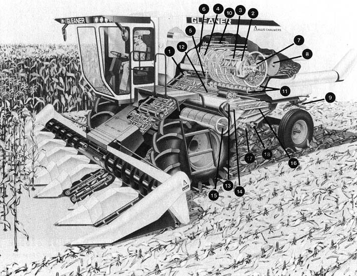
The transverse
flow rotor combine feeds the material directly into the rotor
(1) from the feeding unit. The material then changes direction
in the rotor threshing cage and spirals around the cage toward
the exit at the left end. The rotor (cylinder) (2) is made up
of eight equally spaced rasp bars (3) and mounted inside a perforated
metal cylindrical cage (4). The material is fed perpendicularly
to the cylinder. The first portion of the cage which the crop
is fed into is an adjustable open concave section (5) where most
of the threshing action takes place. Helical bars (6) on the
inside of the cage and the angled rasp bars (3) on the cylinder
then move the material from right to left in a spiral path around
the cylinder. Grain is separated from the material by centrifugal
force. Since the cage is completely perforated, separation takes
place in all parts of the cage. At the left end of the cage,
paddles (7) on the cylinder shaft direct the material to a beater
(8) which discharges the material to a straw spreader (9). To
prevent buildup of chaff on top of the cage, an oscillating cage
sweep (10) is provided. For cleaning, the material passing through
the perforated cage falls into the distribution auger (11) which
deliver it to a pair of accelerator rolls (12). The rolls have
overlapping flutes and turn in opposite directions to accelerate
the material through a band of high velocity air (13), where
initial cleaning takes place, onto the shoe grain pan (14). In
the second stage of cleaning, the fan (15) directs air to the
shaker type cleaning shoe (16) Clean grain falls into the clean
grain auger (17) and is delivered to the clean grain tank. The
tailings pass over the end of the cleaning shoe and fall into
the tailings auger (18) where they are returned to the accelerator
rolls for recleaning. This particular combine has a corn head
on it, but other than that, the functions are identical for harvesting
other crops. |
|
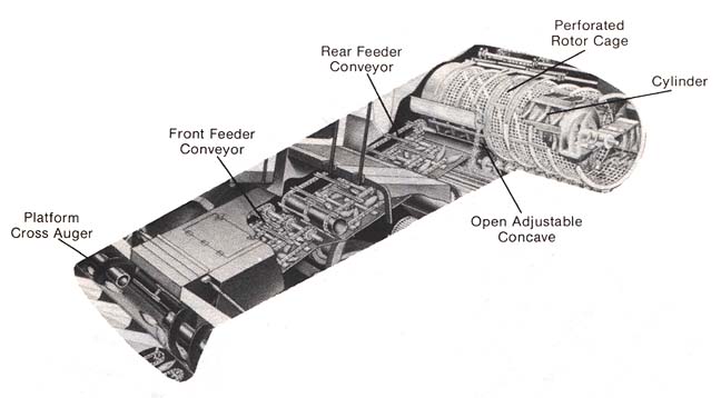
Here
is an enlarged view of the initial feeding section and the cylinder
assembly. |
|
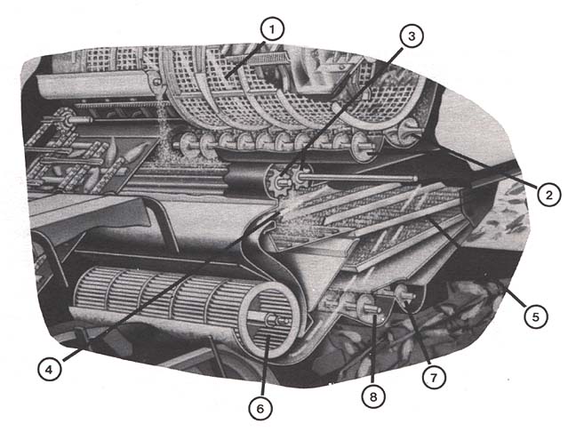
The grain
and chaff fall from the cylinder cage (1) into the distribution
augers (2). The material is then delivered to the accelerator
rolls (3). The accelerator rolls speed movement of the grain
and chaff to over four times the natural rate of falling, past
a blast of air for pre-cleaning (4). Much of the chaff is blown
out the rear of the machine; the remainder of the material falls
onto the cleaning shoe area (5). The air for the two stages of
cleaning is provided by the fan (6). Unthreshed heads fall into
the tailings auger (7) where they are returned to the accelerator
rolls (3). The clean grain then falls into the clean grain auger
(8) and is delivered to the clean grain tank. |
|